Table of contents
What is a state machine? Copy link to clipboard
A state machine is a behavior model. It consists of a finite number of states and is therefore also called finite-state machine (FSM). Based on the current state and a given input the machine performs state transitions and produces outputs. There are basic types like Mealy and Moore machines and more complex types like Harel and UML statecharts.
This introduction gives a short overview of the common basis and the differences between state machine types.
If you are looking for a more detailed introduction to state machines, you should have a look at Statecharts Online
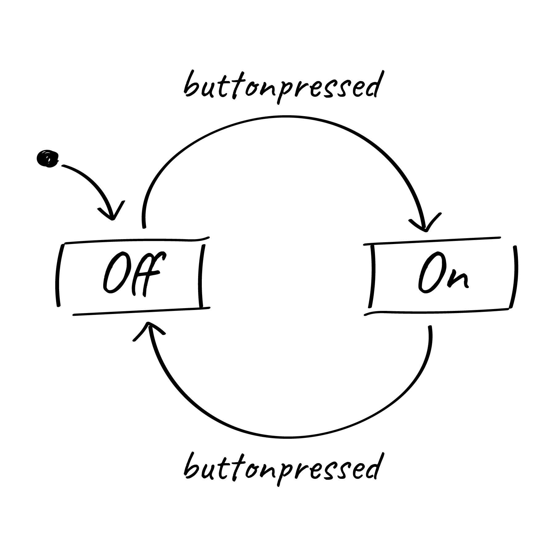
Simple state machine
The basic building blocks of a state machine are states and transitions. A state is a situation of a system depending on previous inputs and causes a reaction on following inputs. One state is marked as the initial state; this is where the execution of the machine starts. A state transition defines for which input a state is changed from one to another. Depending on the state machine type, states and/or transitions produce outputs.
Consider the simple state machine above. It consists of two states, Off and On. On is the initial state here; it is activated when the state machine is executed. The arrows between the states denote the possible state transitions. They define for which input a state change occurs. Here, the active state is changed from On to Off for the input buttonpressed, and back again to On for the same input.
Please note: In automata theory an automaton reacts on inputs and produces outputs. There, the terms input and output are usually used for symbols which belong to an alphabet. Modern state machines use an extended definition of inputs and outputs. Inputs can be events like a button click or a time trigger while outputs are actions like an operation call or a variable assignment.
In the following, we will extend the simple switch example to explain the differences between Mealy and Moore machines as well as Harel statecharts and UML state machines.
Moore machines
In automata theory, there are two basic types of finite-state machines (FSM). One of those is called Moore machine , named after its inventor Edward Moore, who introduced the concept in 1956. Moore machines consist of states and transitions. States are able to produce outputs, and the output is determined solely by the current state, not by any input.
We extend the switch example above into a light switch with different brightness levels. The light switch has two buttons, an ON button and an OFF button. Pressing the ON button switches the light on and toggles through the different brightness levels. This behavior is modeled by the state machine below. Pressing a button raises a corresponding event ( ON_pressed or OFF_pressed) upon which the machine reacts with a state change and corresponding outputs. The output of the state machine is simply the brightness level. As in Moore machines only states produce outputs, we need one dedicated state per brightness level:
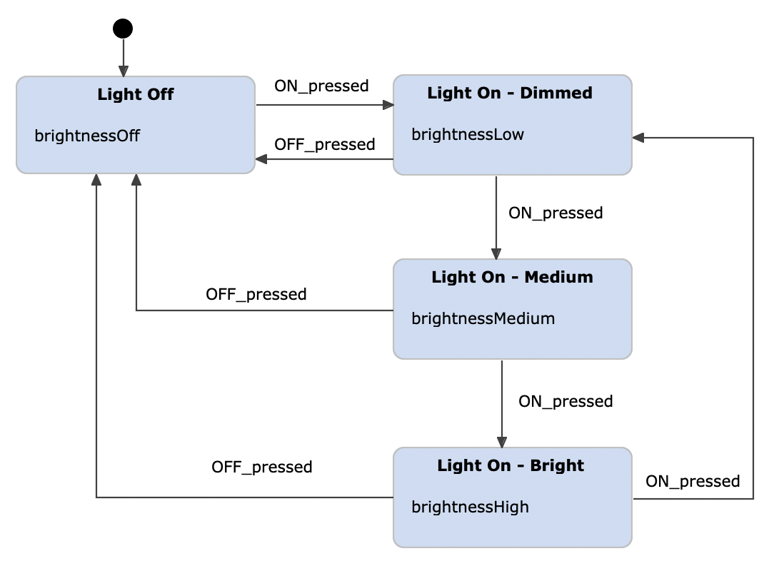
Light switch example as a Moore machine, modeled with itemis CREATE
Mealy machines
Mealy machines were invented by George H. Mealy in 1955. In comparison with Moore machines, Mealy machines produce outputs only on transitions and not in states. This often results in state diagrams with fewer states because more logic can be put on transitions.
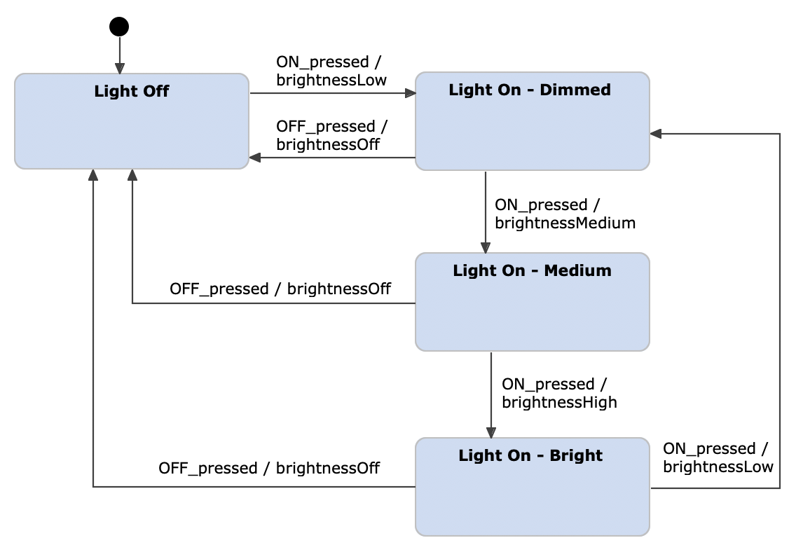
Light switch example as a Mealy machine
Be aware that both state diagrams, the Moore machine above and the Mealy one, describe exactly the same system. Indeed, automata theory states that you can always translate a Moore machine into a Mealy machine and vice versa, without losing any expressiveness.
Harel statecharts
Although Mealy machines can already reduce the number of required states, for complex systems such automatons get easily unmanageable. Or to put it in David Harel’s words:
"A complex system cannot be beneficially described in this naive fashion, because of the unmanageable, exponentially growing multitude of states, all of which have to be arranged in a ‘flat’ unstratified fashion, resulting in an unstructured, unrealistic, and chaotic state diagram."
Harel concluded that " a state approach must be modular, hierarchical and well-structured" and introduced additional concepts like state composition and orthogonality.
He coined the term “statechart”, and defined it as:
"statecharts = state-diagrams + depth + orthogonality + broadcast communication"
So basically Harel statecharts are Mealy/Moore machines extended by further concepts that allow us to model complex systems in a practical way.
Using composite states and sub diagrams, we are able to bring more depth into state diagrams, while keeping the diagrams clear and well-structured. Regions help us to express orthogonality: Different substate machines that can be executed side by side. Events allow us to achieve broadcast communication and give us a strong means to describe complex behavior. Using guards, we can state that a certain event triggers a transition only if a given condition is met. Inter-level transitions, history states, temporal logic as well as entry, exit and throughout actions are further Harel statechart elements.
Harel statecharts can define variables which can be used in input and output expressions. Regarding the light switch example, this allows us to store the brightness level in a variable instead of a number of states. In that way, we can simplify the statechart by merging all Light On states into one and executing the output actions on a self-transition. Here we just increment the brightness value each time the transition is taken. We use the modulo expression to ensure the brightness value stays between 1 and 3. This has the benefit that we can change the number of brightness levels without adding new states.
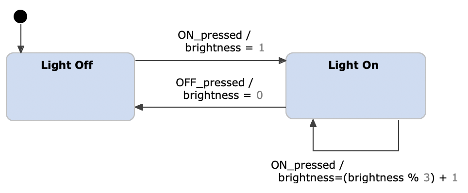
Light switch example as a Harel statechart
To showcase the use of composite states we extend the light switch example by a motion detection mode. When the
MOT button is pressed, the motion sensor is activated. Once the sensor detects any motion (event
motion_detected), the light is switched on at the highest brightness level (
brightness = 3). This can be modeled with a composite state that groups the two states
Motion Detected and
No Motion Detected together.
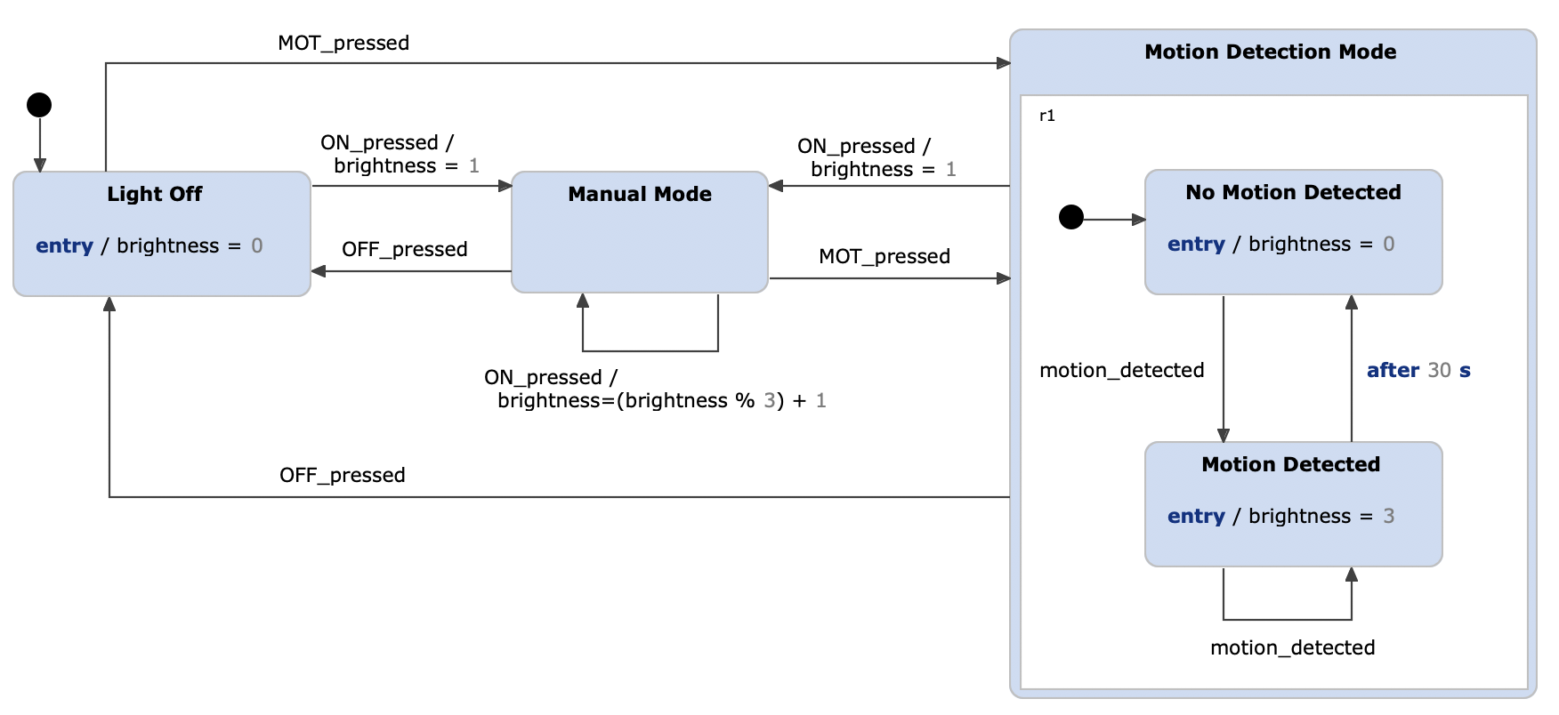
Extended light switch example as a Harel statechart with composite states
Please also note that Harel statecharts combine the characteristics of Mealy and Moore machines, hence outputs can be produced by states as well as transitions as indicated in the statechart above.
We can even go one step further and hide the logic of the Motion Detection Mode into a sub diagram. In that way, the system gets more comprehensive as one can directly see the different modes and how to switch between them.
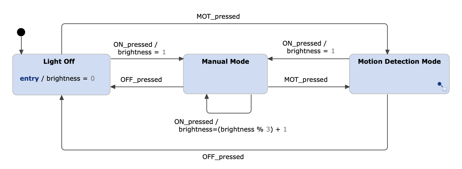
Extended light switch example as a Harel statechart with sub diagrams
Further concepts like orthogonality or history states are left out here for brevity. You can read about them in our quick reference.
The present age: UML state machines
UML state machines are based on the statechart notation introduced by David Harel. Furthermore, the UML extends the notation of Harel statecharts by object-oriented principles. Mapping this to our light switch example, in UML we can model the possible actions of the light switch as a type with operations
turnOn(),
turnOff(),
setBrightness(value) and so on.
The following table illustrates the differences between the previously described types at a glance:
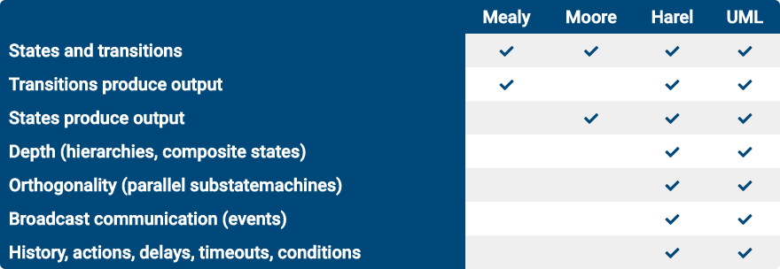
Differences between the state machine types
Learn more about modeling systems with state machines in our free whitepaper:
The statechart examples of this article were designed with itemis CREATE":https://www.itemis.com/en/yakindu/state-machine/, whose documentation you are reading just now. Create statecharts are based on Harel statecharts and are very close but not identical to UML state machines. The concrete differences are explained in the documentation where they exist. itemis CREATE comes with a statechart simulator which allows to directly execute the modeled statecharts. Various code generators translate the statechart into source code.