Table of contents
Modeling the light switch as a statechart Copy link to clipboard
Now let’s model the light switch as a statechart using itemis CREATE. This involves the following steps:
- Creating an Eclipse project. It will serve as a container for the statechart model.
- Modeling the light switch using the itemis CREATE editor. The result will be a static statechart model.
- Simulating the model. We can play around with the model, operate the light switch and observe its behavior.
Creating an Eclipse project Copy link to clipboard
The first step is to create a new Eclipse project that can serve as a container for our model. From the main menu, select File → New → Project...:
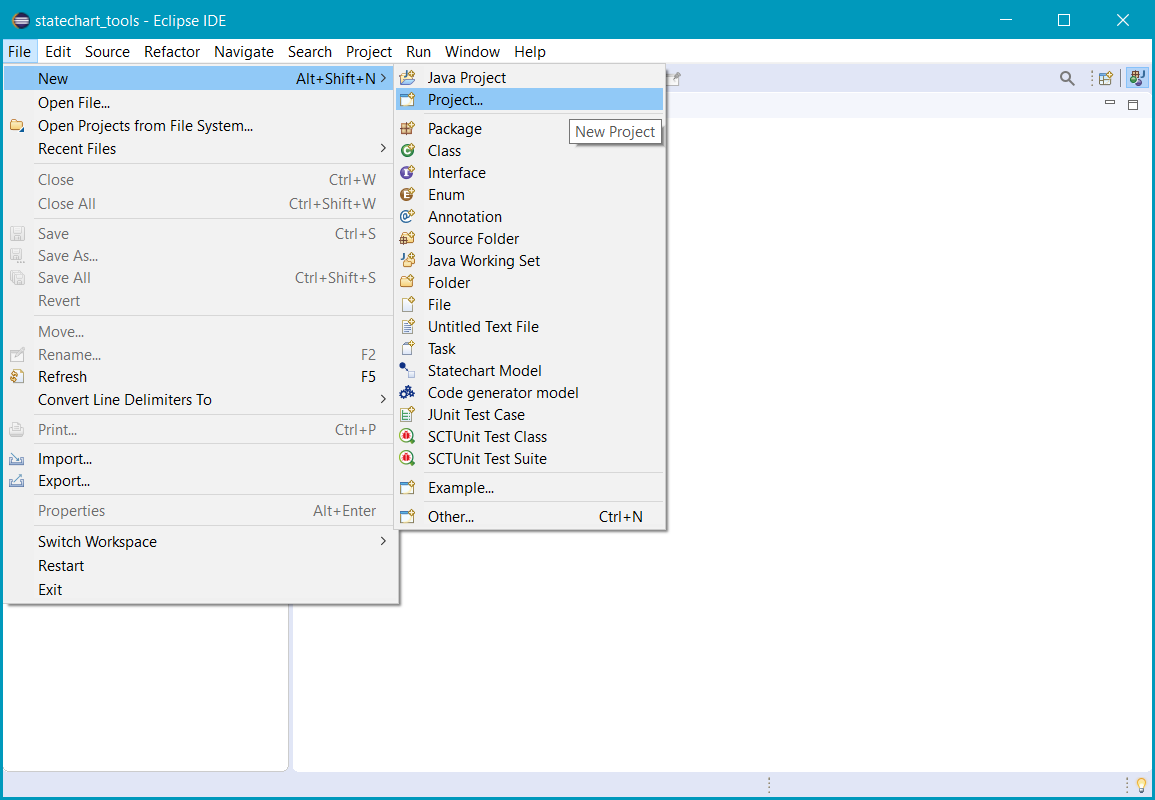
Selecting File → New → Project... in the main menu
The New Project wizard opens, showing a couple of different project types structured in various folders.
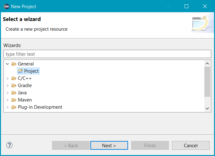
The New Project wizard
Select General → Project and click Next >.
The wizard shows its next page:
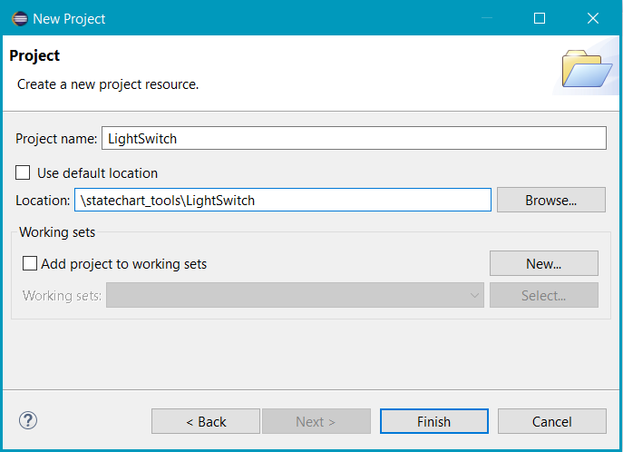
Specifying project name and location
Specify a meaningful Project name, e. g. LightSwitch, and optionally select a Location to create the project in.
Click Finish.
Eclipse creates the new project:
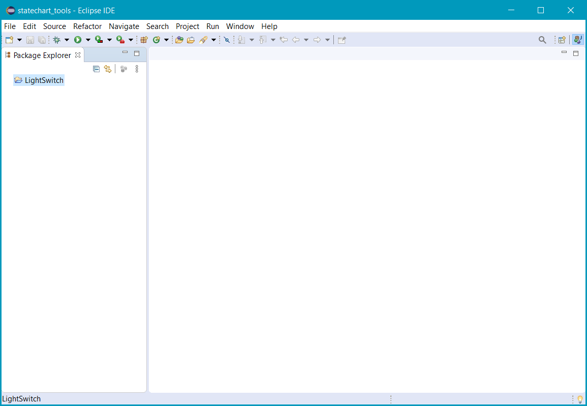
Project LightSwitch created
Creating a folder for the model Copy link to clipboard
Now that we have created the Eclipse project, we can establish the statechart model of the light switch. It is good practice to use a separate directory for models, so let’s create a new folder called model.
Right-click on the project’s root, i.e., on LightSwitch, then select New → Folder from the context menu.
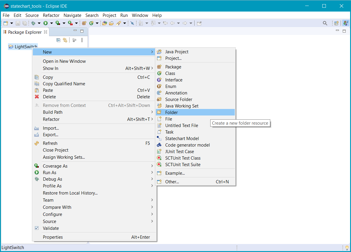
Selecting New → Folder in the context menu
The New Folder wizard opens:
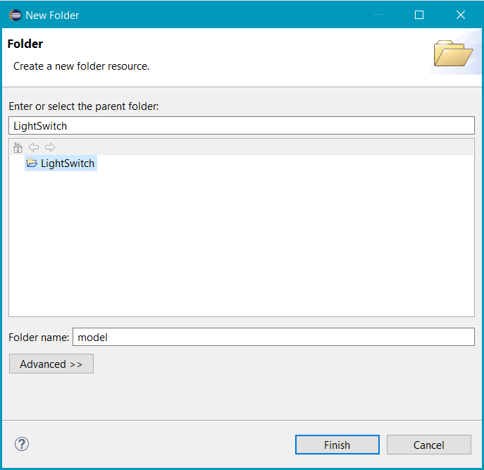
The New Folder wizard
Give the model folder a reasonable name, e. g. model, and type it into the Folder Name text field. Then click Finish.
The new model folder is created and appears in the Project Explorer view at the left.
Starting with an empty statechart model Copy link to clipboard
Using the itemis CREATE Statechart wizard Copy link to clipboard
Now we are going to create an empty statechart model in the model folder. Right-click on the model folder and select New → Other in the context menu:
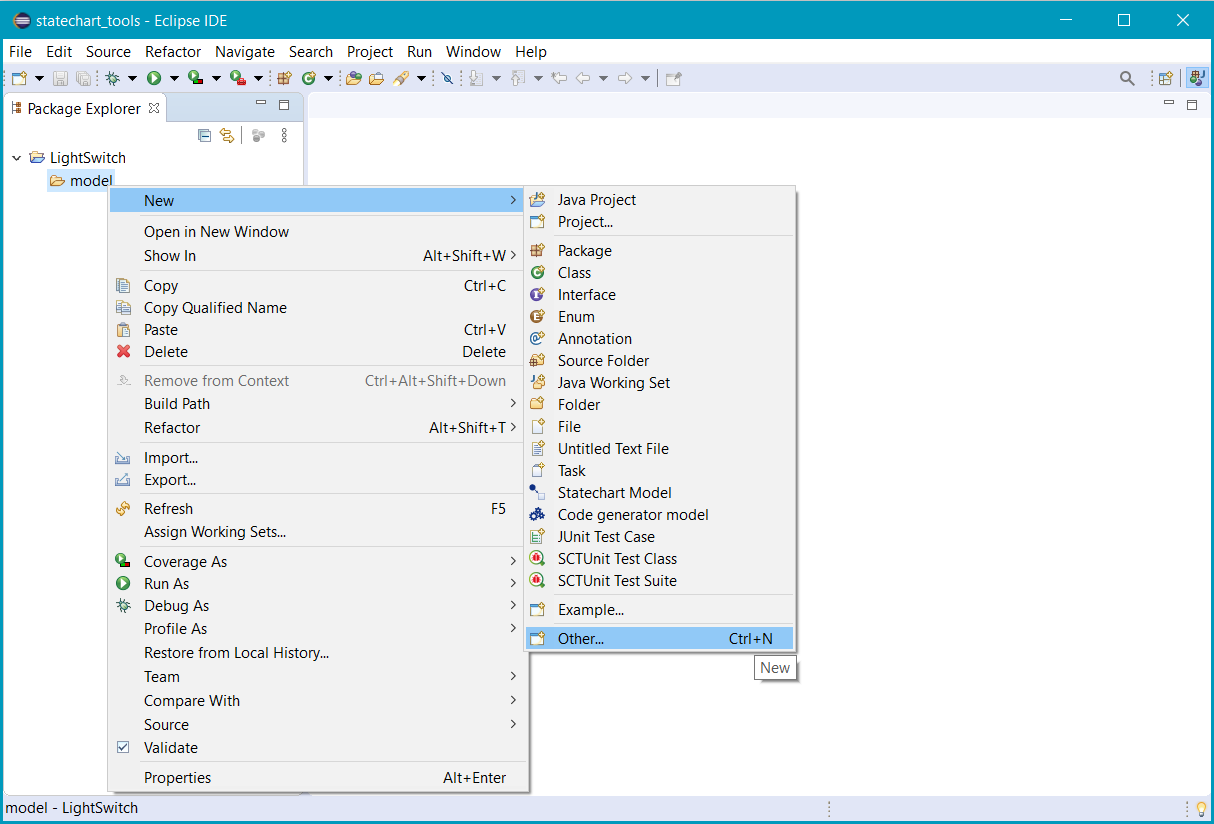
Selecting New → Other in the context menu
The New wizard opens. Select itemis CREATE → Statechart model
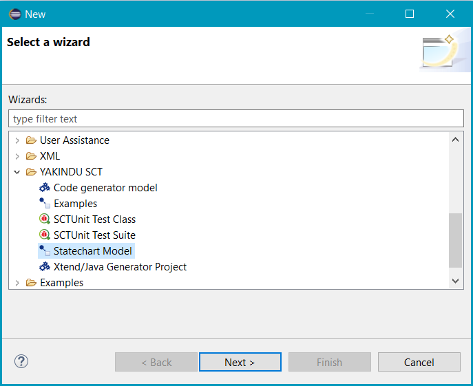
Selecting itemis CREATE → Statechart model
Click Next >. The wizard shows the New itemis CREATE Statechart dialog:
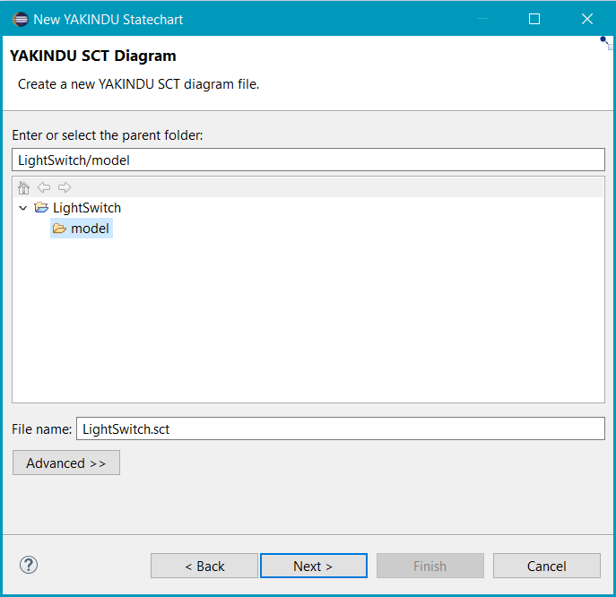
The New itemis CREATE Statechart dialog
The dialog asks you for the project, the directory, and the name of the model file to be created. Eclipse project and directory should be preset correctly already. In our case the corresponding text field contains LightSwitch/model which means the directory named model is in the LightSwitch project. If you want, you can change the preset values.
The default file name in the File Name field is Statechart.ysc, however. You should change that to something more meaningful. In our case we type LightSwitch.sct into the File name field, see the screenshot above.
Click Next.
In the next dialog, in the dropdown menu you can select the domain you want to create a statechart for. A short description helps you to decide for the right domain for you, depending on your needs. In this example, the Default Domain is selected.
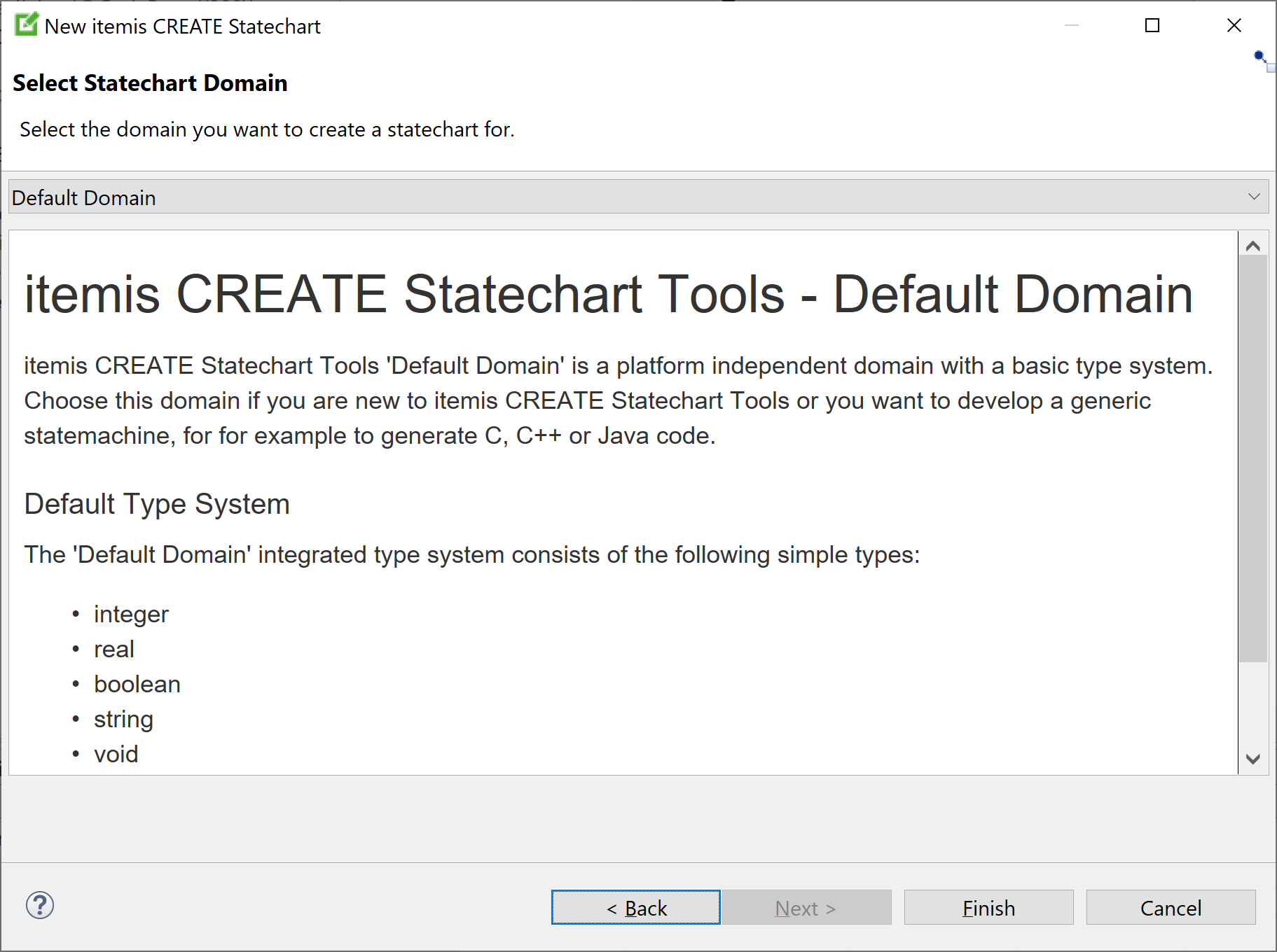
Click Finish.
Since there’s a dedicated perspective for statechart models, Eclipse asks you whether you want to change to it now or not:

Dialog Confirm Perspective Switch
Please answer the question regarding switching to the itemis CREATE Modeling perspective by clicking on the Yes button. The itemis CREATE Modeling perspective has a graphical editor for statechart models, and you will need it to create and modify them. On the other hand your answer really doesn’t matter that much, because you can switch perspectives at any time. If you check Do not offer to switch perspective in the future before clicking Yes, Eclipse will never ask this question again, at least regarding the itemis CREATE Modeling perspective.
Please note: If the Confirm Perspective Switch dialog does not appear as described above you probably have already confirmed Do not offer to switch perspective in the future once before.
The initial model Copy link to clipboard
An empty statechart is created and displayed in the statechart editor in the middle of the Eclipse workbench. In the screenshot below the statechart editor is marked by a red rectangle. Subsequently, we will use the statechart editor to graphically develop the light switch statechart.
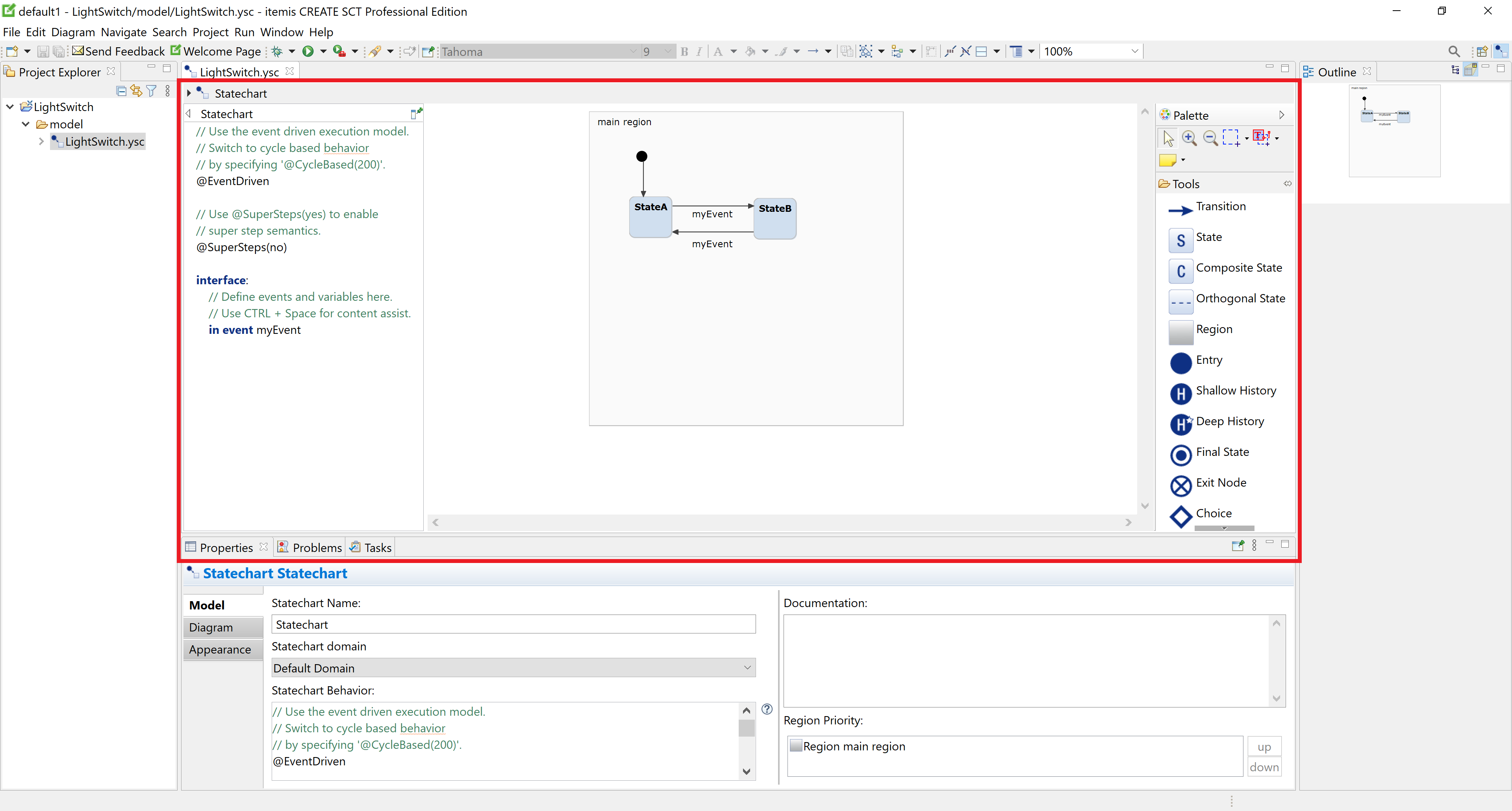
The statechart editor
Actually the new statechart isn’t really empty. It already contains the initial state (a small filled black circle), two “normal” states, and three transitions.
Let’s start our editing with a simple operation, and delete the state called StateB. To do so, just right click on the state and select Delete from Model. Alternatively, you can just press the DEL key on your keyboard.
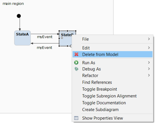
As you can see not only the state, but the transitions connected to it had been deleted. This is the expected behavior, but let’s get back to transitions in a later part!
Giving a state a name Copy link to clipboard
As we have seen, the created state has the default name StateA. You can rename any state depending on your requirements.
Remember our light switch example? The first requirement demands the switch to be off initially. The state is reached from the initial state immediately, so it is appropriate to name it Off.
Double-click on the string
<StateA> in the state object. The string turns into a text input field with
<StateA> being highlighted:
|

|
Type the state’s new name, i.e.,
Off:
|

|
Hit the
[Enter] key or click anywhere outside the text field. Bingo! The state now has a proper name:
|

|
| However, since the state box’s size is smaller than before now while the box’s left position remains unchanged, the graph looks crooked. | |
| We can improve it by dragging the state box a little bit to the right. When it is centered below the initial state symbol, a vertical blue line appears giving the user a visual hint: |

|
| Drop the state box at this very place, and everything looks much better now: |

|
| Alternatively, we could have used the state box’s handles to resize it. However, we just deselect the box by clicking elsewhere: |

|
Creating a state Copy link to clipboard
With the Off state only, the light switch statechart isn’t complete yet. We also need an On state, and we going to create it now.
| In order to add another state, move the mouse pointer to the Palette compartment at the right-hand side of the statechart editor. Click on the State symbol in the palette without releasing the mouse button, and drag the symbol over to the editing area. |
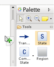
|
| Release the mouse button over a gray area, a region: |
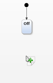
|
| The new state appears in the model graph: |
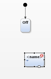
|
| Rename the new state to On. Vertically align it to the Off state, if you like: |
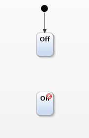
|
| You’ll notice that the new state is showing an error marker. The reason is that it is not yet possible to reach the On state. | |
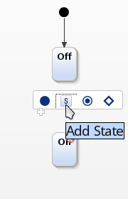
| Before we’ll go on and fix that problem, here’s another way to create a new state. When you are hovering with the mouse pointer over the main region, i.e., the large rectangle with a gray background, a pop-up menu shows up. If you click on the ‘S' symbol in that menu, a new state will be created. Other options in this menu are to create an initial state, a final state, or a choice. |
|
Statechart validation Copy link to clipboard
Error markers in the model graph Copy link to clipboard
In the previous section, after dragging the new state into the editing area and before you gave a name for it, the state had a small filled red circle containing a white ‘X' attached. This is an error marker and tells you that something is wrong with your model, particularly with the object it is attached to. Let’s create a new state, but don’t give a name for it, to guide you through the basics of the error display.
Error markers in the project explorer Copy link to clipboard
The error marker is also shown in the Project Explorer view at the left-hand side of the main window. In this way you can see immediately which of your projects contain errors. Click on the small show/hide symbol (triangle) left of a project’s or any other resource’s name to show or hide its respective contents. By doing so, you can quickly encircle the directories and files that are affected by errors. In the screenshot above we have clicked open the LightSwitch project and the model directory, showing the error is in the LightSwitch.sct file.
Validation principles Copy link to clipboard
This error marker exemplifies itemis CREATE' model validation capabilities. Statechart validation includes syntactical and semantical checks of the whole statechart. For example, a statechart is checked for unreachable states, dead ends, or references to unknown events. These validation constraints are checked during editing. In case any constraints are violated, error or warning markers are attached to the faulty model elements. Thus, the user receives direct and immediate feedback on the validation state of his statechart.
Hovering with the mouse over the error marker in the statechart editor reveals what the problem is. A small pop-up appears and displays the error description: "A state must have a name."
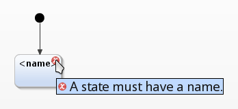
An error marker and a pop-up window explaining it
Error markers in the “problems” view Copy link to clipboard
An alternative place to see error messages is the Problems view. This view has the particular advantage to comprise all notifications in a clearly arranged list form, see the screenshot above. It displays:
- A summary comprising the total number of errors, warnings, and others. In our case we have one error and nothing else.
- Zero or more lists containing errors, warnings, and other types of messages, if available. In our example there is just a single list containing error messages. Click on the show/hide symbol to show the message list’s contents or the list’s header only.
Double-clicking on an error message in the Problems view brings you directly to the erroneous object.
That’s all for now! This knowledge can help you in the future to speed up the fixing of errors in your projects. Let’s delete the incorrect state and move on to the next part to create our virtual light switch!
Creating a transition Copy link to clipboard
As we have seen above, the On state is not reachable as of yet. So let’s model switching the light switch from “off” to “on” as a transition leading from the Off state to the On state.
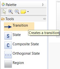
| In the Palette, click on the Transition symbol. The symbol’s background turns blue. |
|
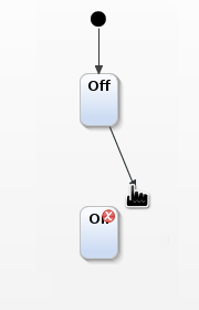
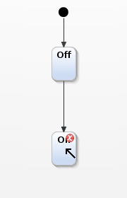
| Click on the Off state, but don’t release the mouse button. Drag the mouse pointer towards the On state. The arrow representing the transition to be established is drawn. |
|
| Once the mouse pointer reaches the target state, it changes its shape. |
|
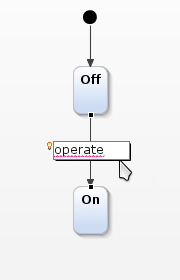
Releasing the mouse button establishes the transition. A text input field to specify event trigger, guard condition and effect appears. We want the transition to be triggered when the light switch is operated, so let’s type
operate into the text field.
|
|
| If you suspect that something is not in order, because the input text is underlined in red, you are right. We will explain and deal with that in a minute. | |
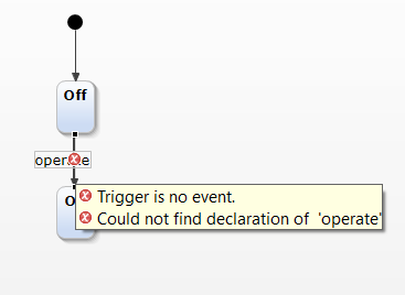
| Clicking anywhere outside the text field terminates the editing mode: |
|
The event trigger operate is flagged as an error. The reason is that an event with that name is not known yet. To change that:
Double-click into the definition section on the left-hand side of the statechart editor. The section becomes an editable text field.
Modify the existing text to the following:
interface:
    in event operate
The keyword
interface makes the following definition of the
operate event belong to the external scope, thus we can interact with it throughout the simulation. The latter is explained in section
"Internal scope".
Click anywhere outside of the text field, which terminates editing the definition section. The statechart editor digests the definition, recognizes the definition of the operate event, and validates the model as being okay:
![Creating definitions [1] Creating definitions [1]](https://www.itemis.com/hubfs/solutions/itemis-create/documentation/images/tuto_compr_150_operate_event.png)
Creating definitions [1]
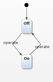
In its current state the model would not allow to turn the light switch off again, which is somewhat unsatisfactory. Operating the light switch while it is on should turn it off again. Let’s model this by adding another transition. It should lead from the source state On to the target state Off.
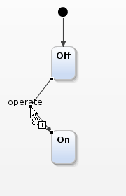
| However, in order to not get two straight lines being close together in the graph, let’s first make some room and turn the present line into an arc. Move the mouse pointer over the transition line, but not over the text. The mouse pointer changes its shape to indicate that you can insert a control point. Click and hold to add the control point, then drag it to an appropriate position. |
|
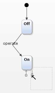
| Now let’s insert the second transition. This time we won’t use the palette, but instead use another method. Hover the mouse pointer over the source state, i.e., On. An incoming and an outgoing arrow appear, both with a handle. Click and hold the handle of the outgoing arrow and drag it to the Off target state. |
|
Upon releasing the mouse button the transition is established. Type
operate as the transition’s event trigger into the text field. Reshape the transition arrow to make the graph look nice.
|
|