Table of contents
Multi state machine modeling Copy link to clipboard
The behavior of large systems is often too complex to be captured by a single statechart. So if a statechart gets too large you should think about splitting it into two or more smaller parts. Beside the fact that the smaller state machines are easier to handle and maintain there are additional reasons for using multiple state machines instead of single monolithic ones:
- Separation of concerns enables a better software architecture.
- State machines can be reused in different contexts. So if you have identical copies of sub states spread around your state machines then this could be a good starting point.
- If you build a distributed system then you require separate state machines for the different nodes.
This chapter describes how you can use itemis CREATE to model and simulate a system which consists of multiple collaborating state machines and how you can embed a statechart as a sub machines into another statechart. This chapter introduces all relevant concepts using an example.
The example is a traffic control of a street crossing using traffic lights. While a single traffic light is not so complex the coordination of different traffic lights on a crossing is a good example to highlight the collaboration between different state machines.
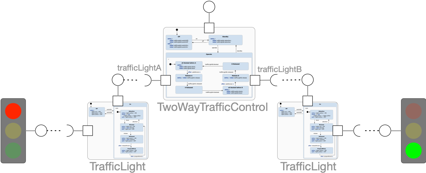
The example consists of a system of three state machine instances. There are two instances of the statechart TrafficLight . Each instance just cares about controlling the different modes of a single traffic light. The TwoWayTrafficControl coordinates both traffic lights and makes sure that the traffic is always safe by making sure that no two traffic lights are green at the same time.
Referencing state machines Copy link to clipboard
First of all – in order to enable collaboration between separate state machines it must be possible that state machines can reference other state machines. To establish such a reference two steps are required:
- The external statechart must be made visible by defining an import scope using
import: "xyz.sct"in the statecharts declaration area. Specify relative paths if the statecharts are not located in the same directory. - Define a variable of the desired state machine type:
var otherMachine : SomeMachineType
For our example statechart TwoWayTrafficControl the declarations look like this:
import: "TrafficLight.sct"
interface:
    var trafficLightA : TrafficLight
    var trafficLightB : TrafficLight
According to the steps described above the statechart TrafficLight.sct is imported. As two instances of this referenced statechart are required, two variables are defined. So if you want to implement a three or four way traffic control you can simply define as many variables for state machine references as you require.
State machine types and instances Copy link to clipboard
A statechart does not only contain the definition of behavior. It also includes structural properties like its declared variables and events. These define its public interface and this interface is represented by a type.
Lets take a look at the example statecharts to get an idea how the state machine types look like:
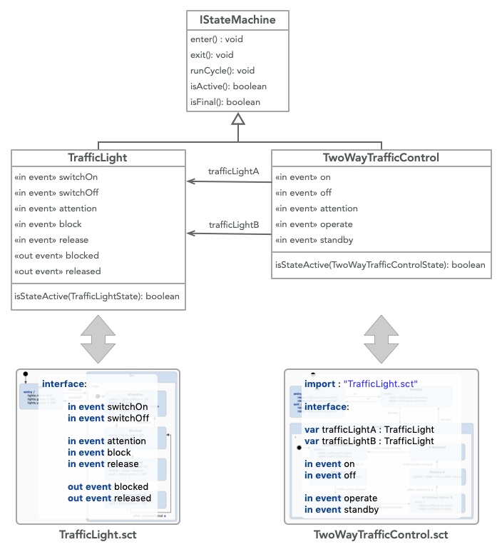
The statechart
TrafficLight.sct defines the type
TrafficLight and the statechart
TwoWayTrafficControl.sct defines
TwoWayTrafficControl. The types include all members defined in the statecharts declaration section. The variables which are of type
TrafficLight are references to instances of this type.
You should know the following facts about state machine types:
- Each statechart has its own type. This type has the same name as the statechart.
- The state machine type is a class type. All members defined in the statechart’s default interface are direct members of this type.
- These members can be variables, events, and operations.
- The type members have the identical name as defined in the statechart.
- State machine types used in variables, events and operations are always reference types.
- Named interfaces are owned by the state machine and are represented as a member with the interface name as name.
- These named interface members are complex types which include all members defined in the interfaces.
- All declarations of the internal scope are not exposed through the state machine type.
- The state machine type inherits from the abstract type
IStatemachine. This type defines additional life cycle operations which are implemented by each state machine. - Each statechart owns an additional enumeration type named
<StatechartName>States. It defines an enumeration value for each state of the statechart.
If you know the state machine code which is generated from statecharts then you will discover that the definitions of the state machine types directly match the definitions of the generated code.
State machine types are always used as reference types. This implies that the state machine which defines a variable of a state machine type does not own the state machine instance. It will never be created by the state machine itself.
As a state machine type is a regular type you can use it like any other type. So you can assign state machine references to variables, use it as event payload, pass it as operation parameter, or use it as an operation’s return value.
Variables of state machine references can be reassigned. A valid value is
null.
null is the default value
after initializing a state machine.
Sending events, receiving events, and accessing variables Copy link to clipboard
A state machine reference can be used to interact with the referenced state machine. All elements which are exposed by the state machine type can be used:
- Raise in events on the referenced state machine.
- React on out events from referenced state machines.
- Get and set variables (including referenced state machines).
The statechart TwoWayTrafficControl raises different events on the referenced state machines.
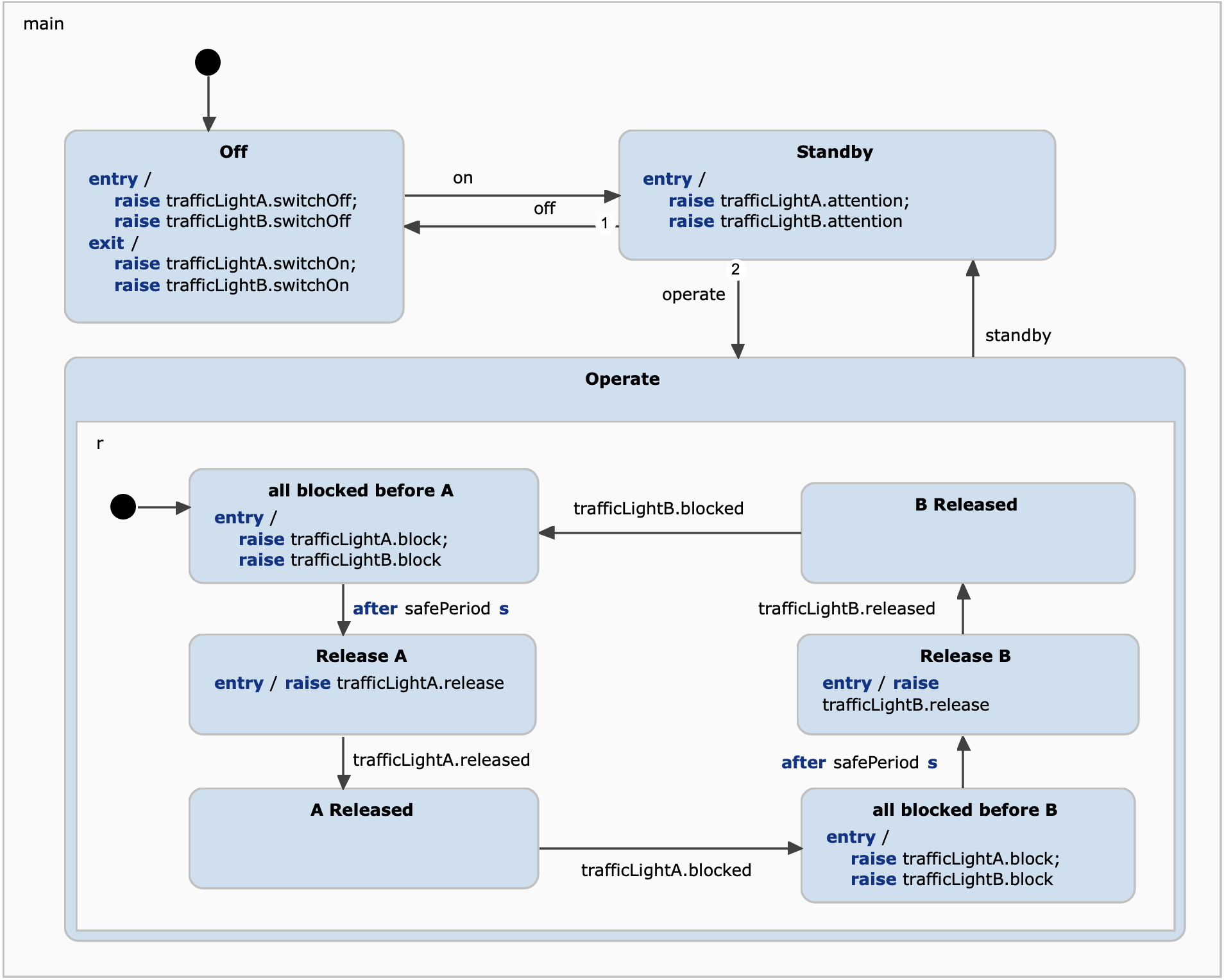
Different states (like
Release A) also use outgoing events (
trafficLightA.released) as transition triggers.
A loosely coupled architecture makes use of asynchronous message passing and this perfectly matches to statechart events. A statechart which raises an event should not make any assumptions when the event is processed.
Accessing variables implies a tighter coupling of state machines as these are accessed in a synchronized fashion.
As an example the statechart TwoWayTrafficControl could configure the TrafficLight state machines using variables that these provide.
entry / trafficLightA.config.realeasePeriod = 60
Here the v ariable releasePeriod is set as an entry action. releasePeriod is defined by the named interface config thus it is accessed in two step using the dot expression ‘.’ .
Controlling a state machines life cycle Copy link to clipboard
In addition to the events and variables which are declared by the statechart, also additional life cycle operations exist. As explained before (see type
IStatemachine in previous chapter), they implicitly exist for each state machine and can be used to control its life cycle.
| operation | purpose |
| enter() : void | An inactive state machine can be activated by calling this operation. During activation the initial state will be activated and all required entry actions are executed. A state machine is inactive by default after creation. |
| exit() : void | A call to exit deactivates an active state machine. During exit, all active states will be exited and all relevant exit actions will be executed. After exit, no state is active. |
| isActive() : boolean | Returns true if the state machine is active and false otherwise. A state machine is active if there is at least one active state. This operation can be used in guards to test the life cycle state of a state machine. |
| isStateActive(state) : boolean | Can be used in guards to check the activation of a specific state. The state parameter must be of the state machines state enumeration type. |
| isFinal() : boolean | Returns true if all active states are final states. The final state won’t change until the state machine is exited and reentered. This operation can be used in guards to check if a state machine has finished its work. |
| runCycle() : void | Performs a state machine run-to-completion step. If a state machine takes full control of a cycle-based state machine then it has to decide when the run-to-completion step must be executed. |
| triggerWithoutEvent() : void | For EventDriven statecharts, it performs a state machine run-to-completion step without raising any event. It can be also used by the client code. |
Using these operations implies a tighter semantic coupling of separate state machines. It is the basis for the implementation of sub state machines as described in the following chapter.
An example for using life cycle operations is given in:
Defining sub state machines Copy link to clipboard
A common concept for structuring statecharts is the decomposition into different sub state machines. This is a concept that you can find in modeling languages like the UML and others.
The basic idea is that a state machine which is assigned to a state as sub machine is executed as if it is part of the enclosing state machine. This means its life cycle is coupled to the life cycle of its owning state. It will be activated when its parent state becomes active, and will be deactivated when the parent state deactivates.
Such a sub machine pattern can be defined using the life cycle methods introduced in the previous chapter. The pattern for using sub state machines looks like this:
entry / otherMachine.enter
oncycle / otherMachine.runCycle
exit / otherMachine.exit
The call to
runCycle is only required if the referenced state machine is cycle-based. The equivalent is the following statement:
submachine otherMachine
The
submachine statement is not only a shortcut. It is more expressive, less verbose and avoids errors by applying higher level validations. You can simply use this statement like any other within the state. Using it is recommended when you want to use sub state machines.
If the referenced state machine is event-driven, then the
triggerWithoutEvent operation can be called, which will perform a run-to-completion step without raising any event.
This allows the guard conditions to be evaluated and the transitions to potentially fire. It is also suitable for firing transitions with the “always” keyword.
So lets take a look how sub state machines can be applied to the traffic control example. The state Operate contains several sub states which control the traffic flow by alternately releasing and blocking the traffic flow of the two directions.

This set of sub states consists of two groups which are similar to each other. The first group consists of the states all blocked before A, Release A, and A Released. The second group is identical except for the fact that A is replaced by B. So the behavior is cloned. Sub state machines can be used to eliminate such redundancies.
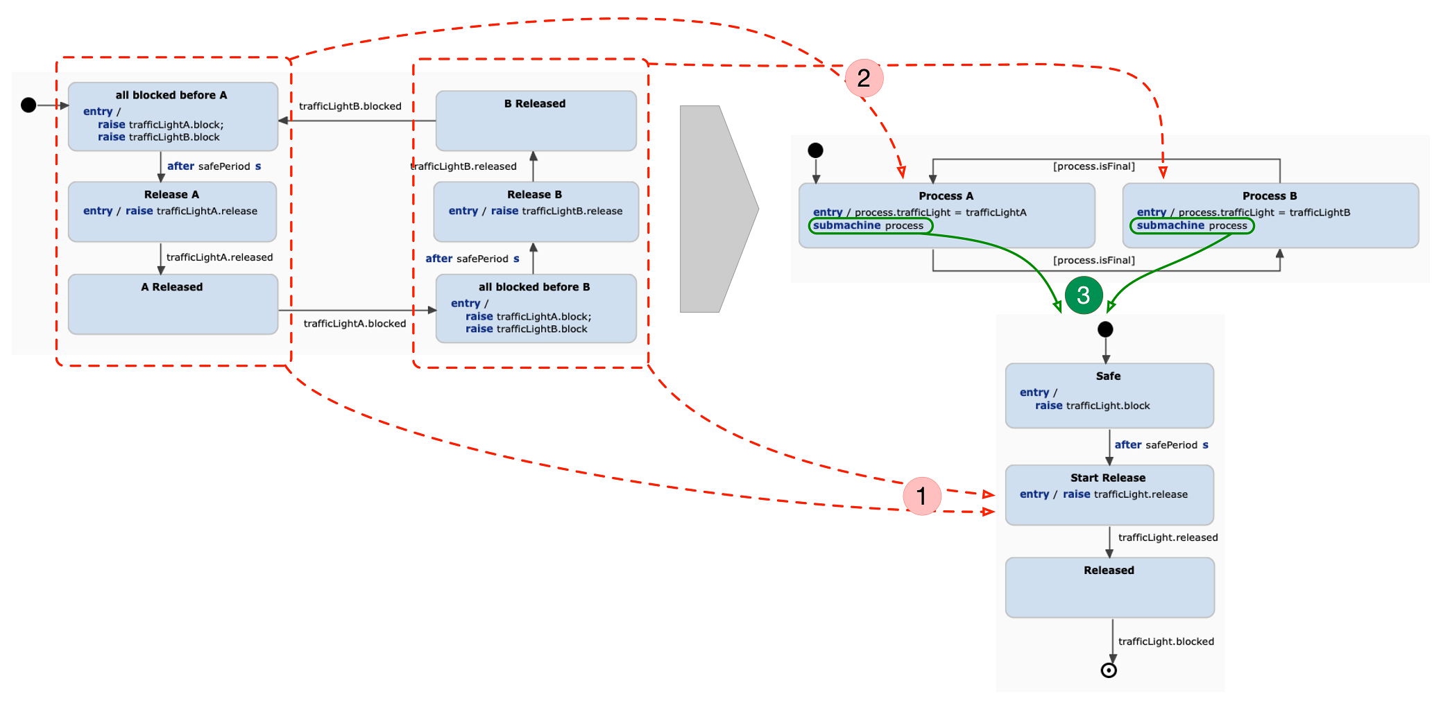
Here, introducing the submachine required three steps.
- Create a new statechart
ReleaseProcess.sct and copy the three states of the identified group. As the statechart should not be specific for a specific traffic light it requires a variable to reference the controlled state machine:
var trafficLight : TrafficLight - Replace each group by a single state. These are Process A and Process B here.
- Integrate the new statechart
ReleaseProcess as a sub state machine.
- This requires an additional variable which holds the reference to the sub state machine:
var process : ReleaseProcess - The new states integrate the submachine. On entry, the new process state machine is configured with the proper traffic light state machine:
entry / process.trafficLight=trafficLightA - The sub machine is hooked into the state:
submachine process - The transitions of the two states are triggered when the
ReleaseProcess state machine has finished its work and is in a final state. The guard is defined on the transitions:
[process.isFinal]
- This requires an additional variable which holds the reference to the sub state machine:
This results in the following TwoWayTrafficController and ReleaseProcess state machines:
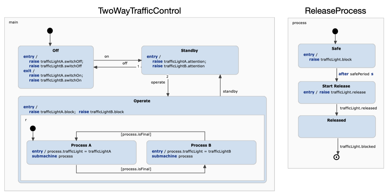
This example shows a typical scenario where using sub machines makes much sense. Here, sub machine controls a process which consists of several steps. Here, it just contains a happy case but it may also define error states. This process can be reused easily if the state machine should be extended to a 3 or 4-way traffic control. So setting up a 4-way traffic control in the initial statechart would require 4x3=12 states while using a sub machine requires 4+3=7 states.
In this example the state machine
process is used as sub machine in both states
Process A and
Proces B. When state machine
process reaches its final state, the state transition from state
Process A to state
Process B will be executed. During this state transition, first,
Process A will be exited. As a result also the sub machine will be exited. Second,
Process B will be entered. As a result, the
process state machine will be configured to use the other traffic light state machine and the
process state machine will be activated by calling its
enter operation. This will activate the initial state
Safe. So the
process state machine is reset to control the next process.
Sub machines are comparable with sub regions and as it is possible to define multiple sub regions for a state it is also possible to define any number of sub state machines. It is even possible that a state defines both – sub regions and sub machines. If both are defined then they are processed according to the execution order:
- In the case of @ChildFirstExecution the sub regions are processed first.
- In the case of @ParentFirstExecution the sub machines are processed first.
Additionally, the order of the
submachine statement within a state’s behavior definition is relevant for the execution order:
- Submachines are entered, exited, and executed (runCycle call) according to the order of the
submachinestatements. - Entry actions which are defined before the
submachinestatement are executed before entering the sub machine. Those defined after are executed later. This may be relevant for properly setting up sub machines. - Exit actions which are defined before the
submachinestatement are executed before exiting the sub machine. Those defined after are executed later. This may be relevant for properly tearing down sub machines. - In the case of cycle-based sub machines all local reactions of a state which are defined before the
submachinestatement are executed before executing the sub machine’s run-to-completion step. Those defined after are executed later.
As shown in the example a state machine can be used as a sub machine within different states. The only constraint that must be considered is that these states must be exclusive to each other so that both states can’t be active at the same time. In other words, a machine can only be a sub machine in one active state at once. The subsequent use of a state machine as sub machine is no problem.
Multi state machine modeling principles Copy link to clipboard
The ability to access the state machine life cycle operations which were introduced in the previous chapter provides the basis for the implementation of sub state machine. Nevertheless, the concept of sub state machines defines tight life cycle constraints and this is just one pattern to control a state machine. The life cycle operations can also be used to control state machines beyond the concept of sub machines. So it is possible to enter a machine in a state and exit it in another state.
Future versions of this document will discuss different principles and best practices for multi state machine modeling.
Simulating multiple state machines Copy link to clipboard
The statechart simulation supports the simulation of multiple statechart instances. Simply choose a statechart and choose Run As > Statechart Simulation from the menu.
If the statechart defines variables which refer to other statechart types then the simulation engine will care about setting up the simulation scenario which includes statechart instances of the involved statechart types.
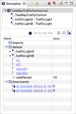
When starting the simulation for the statechart TwoWayTrafficControl the simulation view will list TwoWayTrafficControl.sct as the current simulation session. Additionally, the statechart instances which were created for the simulation session are listed as children of the simulation session.
The first statechart simply has no specific name and is of type TwoWayTrafficControl . The second and third are instances of the statechart TrafficLight. Their name is the name of the variables which are defined by TwoWayTrafficControl as statechart references.
If you click on the statechart instances then a simulation viewer for the specific statechart instance will be opened.
In the detail view below also the variables that reference statecharts are visualized with a statechart icon. You can unfold the details of the referenced statechart by clicking on the grey triangle.
State machine creation Copy link to clipboard
The simulation engine creates statechart instances according to the following strategy:
- create the root statechart instance
- for each defined statechart reference of the instance
- if no instance was created for this reference definition (precludes infinite recursion)
- create a statechart instance of referenced type
- set the reference
- continue with 2.)
- if no instance was created for this reference definition (precludes infinite recursion)
As described in the previous chapters - statechart instances never create other statechart instances. Statecharts are created by the simulation environment.
State machine activation Copy link to clipboard
After all statechart instances were created and connected the simulation engine will activate the root statechart instance. All other instances are not activated. This implies that the root statechart must initiate the activation of the referenced machine instances. This can be done by
- calling their enter methods
- or using them as sub machines.
If this is the case then everything works out of the box. There are additional cases where controlling the referenced statechart’s life cycle is not desired, e.g. to have a system of loosely coupled instances. Such systems typically just send events to each other and are inherently asynchronous. If you run the simulation for one of the involved statecharts then all instances except for the simulation root will never be activated.
In these cases you should setup an additional statechart which controls the life cycles of the loosely coupled state machine instances. This statechart defines the system behavior and thus we call it system statechart.
This case can be illustrated using the traffic light control example. Here, all involved statecharts interact using events. An additional statechart StreetCrossingSystem.sct defines the system behavior. This includes the start up sequence of all involved statechart instances.

The system statechart defines a reference called controller to a TwoWayTrafficControl state machine type. It does not start up everything immediately – what would be possible – but defines a set of states which define different system scenarios. The initial state is Off. In this state no state machine is active. By raising the event startAll the system enters the state On which makes sure that all state machines are active. Mention that the system behavior can access the referenced statecharts of referenced statecharts.
The system behavior also defines an additional state for each TrafficLight state machine instance. Here, a temopary outage of a TrafficLight is simulated by deactivating the machines.
System statecharts can be used to fully control state machines. They can be used to set up complex system scenarios and finally may automate execution sequences to bring the system in a defined state which would require much click work for the user.
Testing multiple state machines Copy link to clipboard
SCUnit supports unit testing of multiple state machines. A SCTUnit test is defined for a state machine type which is the test instance of the unit test.
If the statechart defines variables which refer to other statechart types then the test environment will care about setting up the test scenario which includes statechart instances of the involved statechart types. Here the same instantiation strategy as described for the simulation is applied.
If the statechart under test does not control the life cycle of the referenced state machines, then this can simply be done by the test case itself.
An simple test case for the traffic control example could look like this.
testclass TwoWayTrafficControl for statechart TwoWayTrafficControl {
	@Test operation testStartUp() {
		enter
		trafficLightA.^enter
		trafficLightB.^enter
		assert active (main.Off)
		assert trafficLightA.isStateActive(TrafficLightStates.Off)
		assert trafficLightB.isStateActive(TrafficLightStates.Off)
	}
}
In SCTUnit state machines must be activated explicitly. this is also true for the state machine under test which is a
TwoWayTrafficControl state machine instance. The machine under test is activated by the
enter statement while the two
TrafficLight state machine instances are activated by calling the
enter operation on the reference.
The following assertions check if the initial states were activated. This is done by using the built-in function
active for the machine under test while the referenced machines are tested using the
isStateActive operations.
To be able to call the
triggerWithoutEvent operation for
EventDriven statecharts a variable have to be defined for the statechart with the type of
Statemachine. After that through this variable, every operation defined by the statechart type will be accessible.
Use the SCTUnit built-in functions for the state machine under test and use the operations defined by the state machine types for the referenced state machines.
Generating code for multi state machine systems Copy link to clipboard
If a statechart uses other statecharts then this will be the same on the level of the generated code. You will find dependencies from the generated using state machine type to the the generated used state machine type.
The code generation process does not change when statecharts use other statecharts. Simply define the code generator ( sgen ) files as before. Make sure that the generator properties, especially those that relate to output paths fit together.
p.