Table of contents
Simulating statecharts Copy link to clipboard
itemis CREATE supports model simulation.
Simulating a statechart model means to execute it, raise events manually, have time-based and other events being triggered automatically, and observe the model’s behavior.
You can run multiple state machines in parallel and even multiple instances of the same state machine.
An introduction to simulation is given in section "Simulating the light switch model".
Starting a simulation Copy link to clipboard
You have several options to start a statechart simulation.
Using the statechart model file context menu Copy link to clipboard
The most direct way is to start the simulation based on the statechart model file.
- In the project explorer view, right-click on the statechart model file. The context menu opens.
- In the context menu, select Run As → Statechart Simulation, see figure "Selecting Run As → Statechart Simulation in the context menu" .
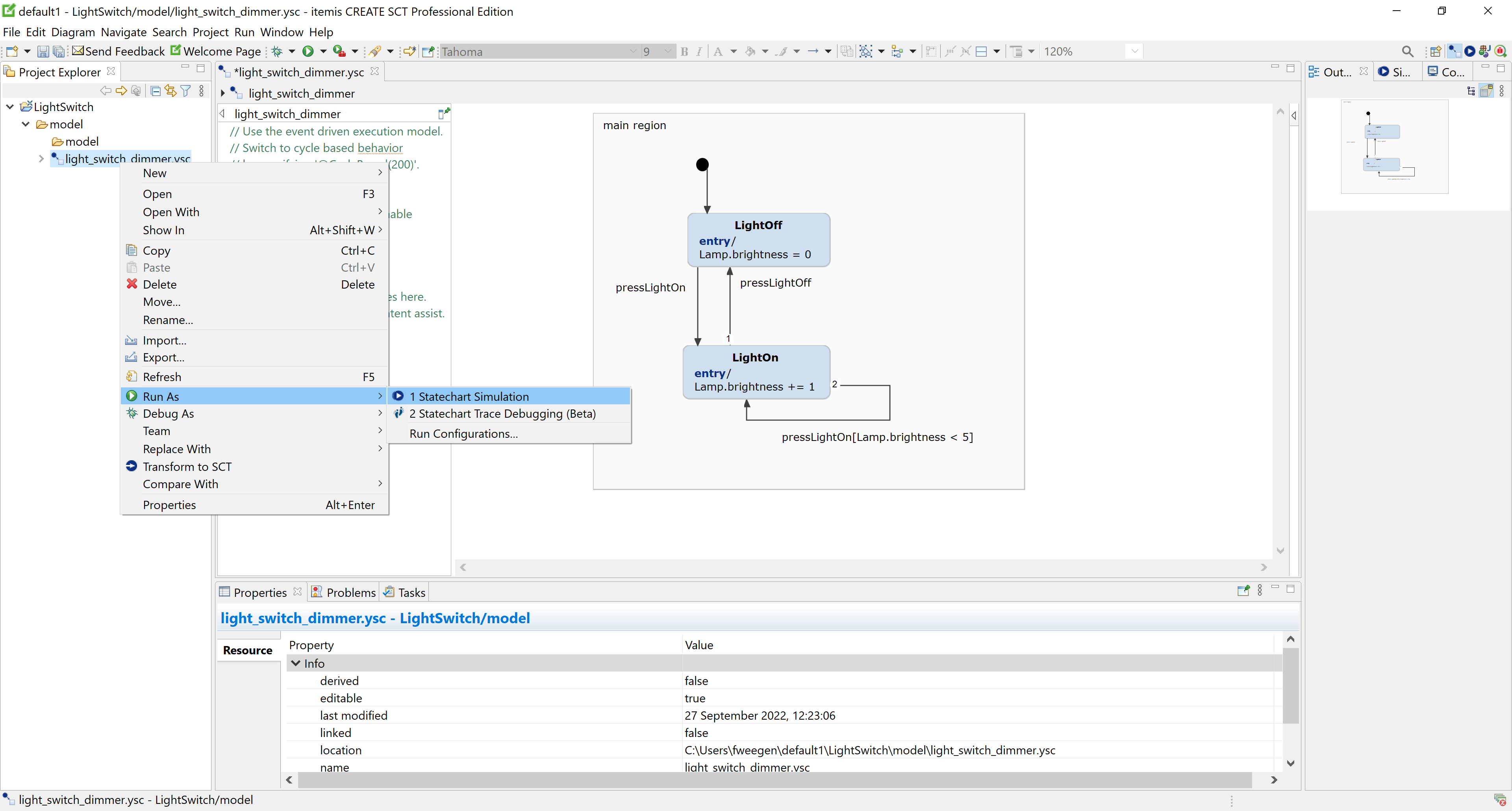
Selecting Run As → Statechart Simulation in the context menu
Repeating the last simulation Copy link to clipboard
In order to re-run the simulation you have most recently executed, simply
- press
[Ctrl+F11]on the keyboard
or
- select Run → Run in the main menu.
To be exact, this operation does not necessarily re-run the last
simulation, but rather the last executed
launch. So if, for example, you first run a statechart simulation followed by running a Java program, then upon pressing
[Ctrl+F11] that Java program is executed once again, not the statechart simulation.
Repeating an earlier simulation Copy link to clipboard
Let’s consider a scenario where you want to execute a simulation that you have run before, but not as the most recently executed launch. So you cannot use the procedure described in section "Repeating the last simulation".
However, as long as you haven’t launched too many other programs in between, chances are good to find your simulation in the history.
Try the following:
- In the main menu, open the Run menu and move your mouse pointer over the Run History entry.
- A submenu attached to the Run History menu entry opens, containing the most recently executed launches. Check whether the simulation you want to execute is available in the submenu. If it is, select it to start the simulation.
Creating and executing a launch configuration Copy link to clipboard
When a statechart is simulated for the first time, a launch configuration is automatically created. A launch configuration describes the parameters used for a particular launch. In case of a statechart simulation, it describes which statechart is to be simulated and the simulation mode (event-driven or cycle-based). For details on how to create and modify a launch configuration, see section "Configuring a simulation".
To execute an existing launch configuration, proceed as follows:
- In the main menu, select Run → Run Configurations…. The Run Configurations dialog appears.
- The list on the left-hand side of the Run Configurations dialog displays all available launch configurations. Select the launch configuration you want to execute.
- Click on Run to execute the launch configuration.
The SC Simulation perspective Copy link to clipboard
The SC Simulation perspective provides selected views that are most useful when running a statechart simulation.
Engaging the SC Simulation perspective Copy link to clipboard
When a simulation starts, the perspective usually changes to the SC Simulation perspective. If this doesn’t happen, you can manually engage the SC Simulation perspective as follows:
- In the main menu, select Window → Perspective → Open Perspective → SC Simulation.
Alternatively, you can do the following:
- In the main menu, select Window → Perspective → Open Perspective → Other…. The Open Perspective dialog appears.
- In the Open Perspective dialog, select SC Simulation.
- Click on Okay. The SC Simulation perspective opens.
Views contained in the SC Simulation perspective Copy link to clipboard
By default, the SC Simulation perspective shows the following views:
- Project Explorer (top-left): This view displays your workspace and projects, folders, and files contained therein. You can also use the Project Explorer to inspect the internal structure of your statechart models.
- Outline (bottom-left): This view is a bird’s eye view on the opened statechart. It also indicates the current viewport for better orientation in large models.
- Simulation (right): This view shows the current state of all variables and events during a simulation. A detailed description is available in section "The Simulation view".
- Breakpoints (right): This view shows a list of all breakpoints. You can use it for disabling, enabling, or removing breakpoints as well as for defining conditional breakpoints.%
Displaying simulation progress in the statechart editor Copy link to clipboard
The SC Simulation perspective also includes the statechart editor. In a running simulation, the statechart editor highlights active states by coloring their backgrounds.
When a transition is taken, the transition arc leading from the source state to the target state flashes briefly in the transition highlighting color. After that, the target state becomes active and changes its background to the state highlighting color. The source state’s background color becomes normal again.
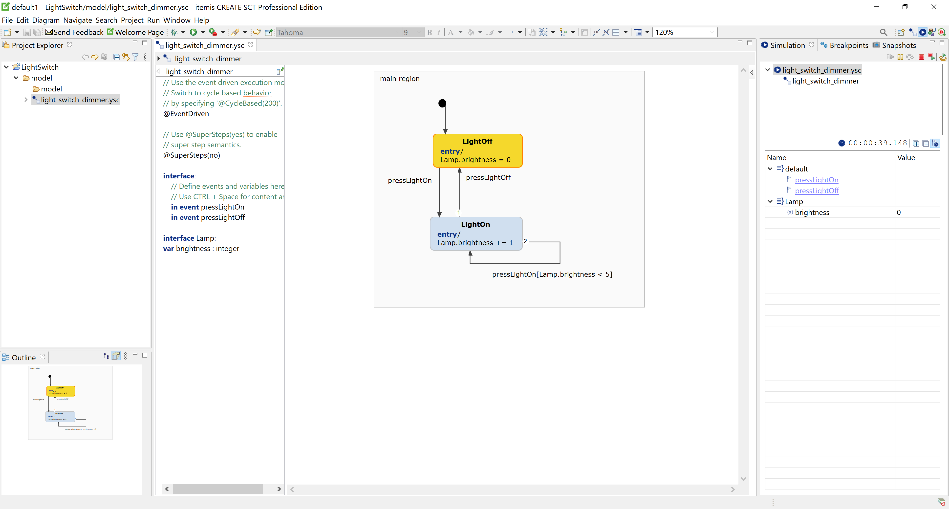
The SC Simulation perspective
The Simulation view Copy link to clipboard
The Simulation view is used to manually raise events and to inspect and modify variables of a running simulation. By default, that view is located on the right-hand side of the SC Simulation perspective, see figure "Simulation view" for an example.
The Simulation view groups events and variables by their interfaces. The unnamed interface appears as default in the interface list. Click on the small triangle left from an interface’s name to show or hide that interface’s contents, i.e., events and variables.
The simulation view also displays
time events, provided the statechart uses time constructs like
after or
every. Press or release the
"show time events" button
 to toggle between displaying and not displaying time events. You can click on a time event to raise it, i.e., you don’t have to wait for 24 hours to elapse in real time until the
"after 24 * 60 * 60 s" transition fires.
You can have multiple simulation instances running at the same time. They may simulate the same or different statecharts. Use the simulation view’s drop-down menu to switch between simulation instances.
A digital clock right from the drop-down menu displays the virtual time elapsed in the simulation. It pauses while the simulation is suspended.
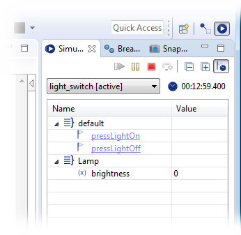
The Simulation view
Please note:
Depending on your screen resolution and font size settings, you might not be able to spot the Simulation view by its name, because the tab containing it is quite narrow and might not provide enough space for displaying the title. Hover over the tabs to reveal their respective titles in a pop-up window.
Figure "The SC Simulation perspective" is demonstrating this: The user has hovered the mouse pointer over a tab that just displays the first letters of its title. However, a pop-up window right under the pointer shows the tab’s full title “Simulation”.
Controlling a simulation Copy link to clipboard
- To terminate the simulation, click on the
Terminate button
 .
.
- To suspend the simulation, click on the
Suspend button
 .
.
- To resume a suspended simulation, click on the
Resume button
 .
.
- Use the
Step Over button
 to execute a single run-to-completion step.
- To terminate the current simulation and run it again from the start, use the
Terminate and Relaunch button
 .
.
- To start a new simulation while keeping the current one active, use the
Restart button
 .
.
Interacting with a simulation Copy link to clipboard
You can interact with a running simulation by manually raising events and by inspecting and modifying variables. You can do so at any point in time, but in most cases you will do it while the simulation “sits idle” at its active state and waits for an event to trigger a transition.
Raising an event in the simulation Copy link to clipboard
To raise an event, proceed as follows:
- In the simulation view, click on the small triangle to open the interface containing the event, if needed.
- Click on the event to raise it for the next run-to-completion step.
If the simulated statechart’s execution semantic is
EventDriven then the simulation view will contain a global event called
triggerWithoutEvent. Clicking on it will call the statechart’s
triggerWithoutEvent operation and with that it will perform a run-to-completion step without raising any event.
Inspecting a variable Copy link to clipboard
To inspect a variable’s value, proceed as follows:
- In the simulation view, click on the small triangle to open the interface containing the variable, if needed.
- The variables contained in the interface are displayed.
Watch the displayed values change as the simulation progresses and actions in states or transitions are executed that modify the variables' contents.
Modifying a variable Copy link to clipboard
To manually modify a variable’s value, proceed as follows:
- If needed, open the interface containing the variable by clicking on the small, hollow triangle left from the interface name in the simulation view.
- Click on the variable’s value. You can edit the value now.
- Enter the variable’s new value and press
[Enter]. The new value is assigned to the variable and replaces the former value.
Configuring a simulation Copy link to clipboard
Section "Creating and executing a launch configuration" describes how to start an existing launch configuration.
The present section describes how to create and configure a new launch configuration for a statechart simulation.
- In the main menu, select
Run → Run Configurations…. The
Run Configurations dialog appears.
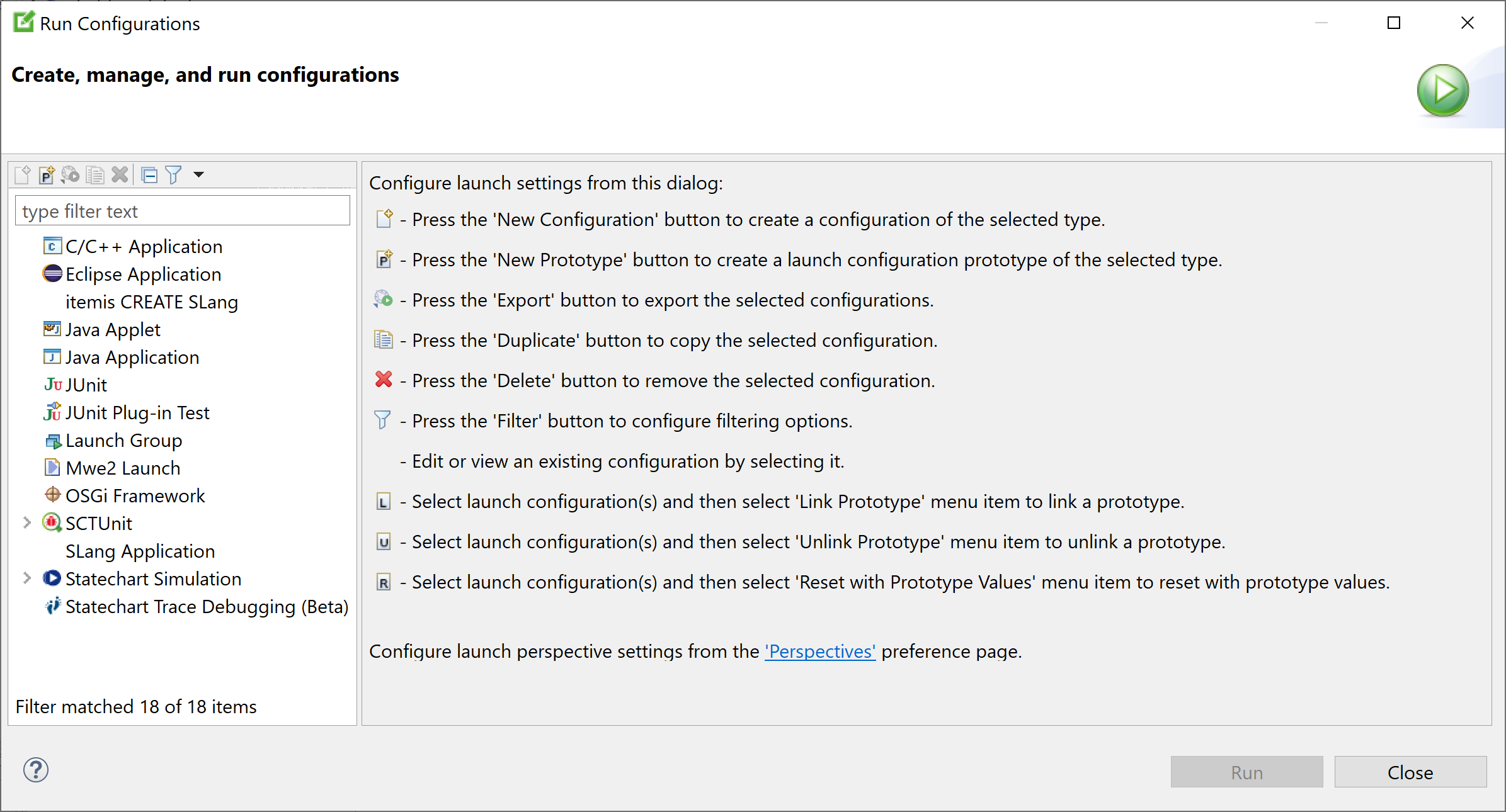
- In the
Run Configurations dialog, right-click on
Statechart Simulation and select
New in the context menu.
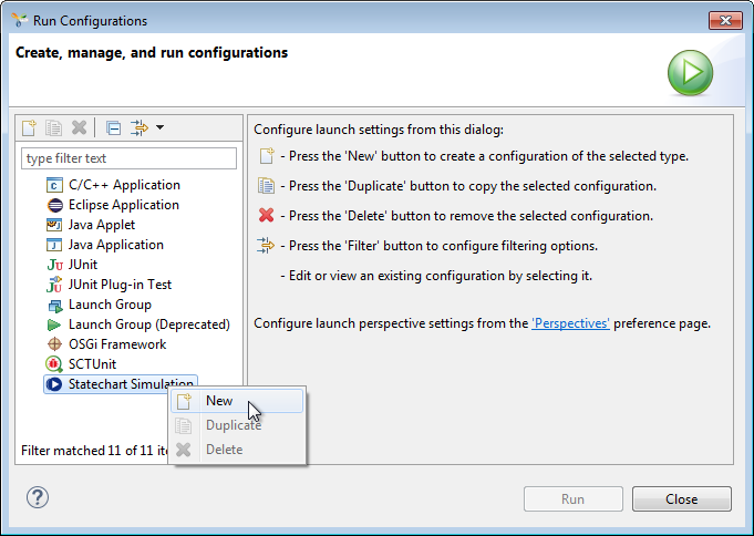
Alternatively, you can select Statechart Simulation and then click on the New symbol near the top-left corner of the dialog.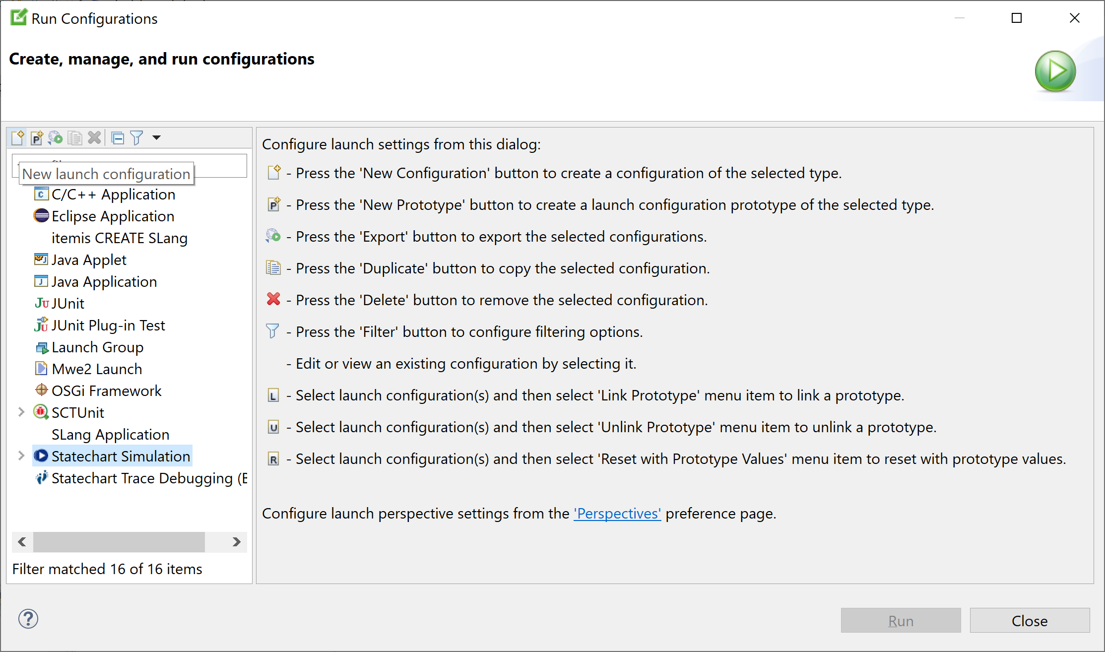
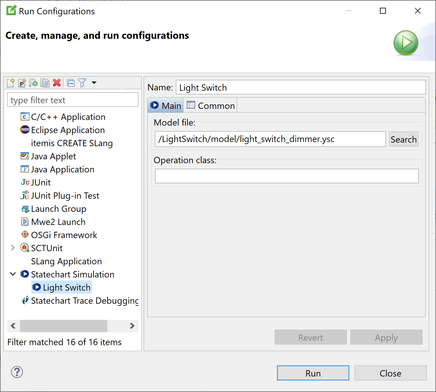
However you do it, a new launch configuration is created and displayed in the main area of the Run Configurations dialog. The launch configuration’s Main tab is opened. - Enter the launch configuration’s parameters as necessary:
- In the
Name text field, change the default name
New_configurationto something sensible, e.g.,Light switch. - In the Model file text field, enter the path to the statechart model you want to simulate. Click on the Search button to browse for statecharts.
- If your model uses Java operations, specify the Java class implementing those operations in the
Operation class text field. If you have multiple Java classes, specify them as a comma-separated list.
- In the
Name text field, change the default name
Please note: Besides the Main tab described above, a statechart simulation launch configuration also has a tab named Common. This tab is a common standard to all types of launch configurations, and it is described in the Eclipse documentation.
In addition to creating new launch configurations, you can also duplicate or delete launch configurations in the Run configurations dialog. Right-click on a launch configuration and select Duplicate or Delete from the context menu.
Debugging with breakpoints Copy link to clipboard
Introduction Copy link to clipboard
itemis CREATE includes two simulator features that increase your productivity considerably when debugging statecharts:
- You can attach breakpoints to states and transitions. If a statechart simulation reaches a transition or state with a breakpoint, it suspends execution of the simulation. A breakpoint can be amended with a condition. Such a breakpoint will suspend the simulation only if that condition is fulfilled, i.e., evaluates to true.
- You can create snapshots of your statechart simulation. A snapshot contains everything making up your state machine simulation at any point in time. It describes the state of the state machine. Snapshots can be saved and restored later in order to continue the simulation from exactly the point the snapshot was taken.
The light switch example Copy link to clipboard
Throughout this chapter we will be using the light switch statechart as an example. It models a lamp which can be turned on and off and also supports various brightness values.
If you press the pressLightOn button, the lamp turns on at its lowest brightness value. If you operate pressLightOn repeatedly, each time the lamp becomes brighter until it reaches its maximum brightness. Pressing the pressLightOff button immediately turns off the light completely. The brightness can only be raised as long as it hasn’t yet reached its maximum value of five. After that, the guard condition disallows to raise it any further.
Here’s the light switch example’s statechart followed by its definition section:
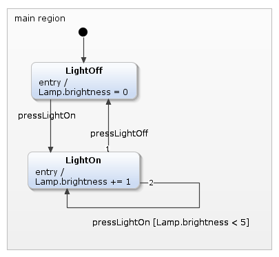
The light switch sample statechart
interface:
    in event pressLightOn
    in event pressLightOff

interface Lamp:
    var brightness: integer
Breakpoints Copy link to clipboard
Breakpoints allow for automatically suspending the simulation when a certain element of the state machine is activated. Optionally, a halting condition can be specified to better control the behavior of a breakpoint. Breakpoints can be set on transitions or states. If a state or transition with a breakpoint is reached, the simulation pauses, and the current state of variable values can be examined in the simulation view. It is possible to change variable values and to trigger events that will be raised when the simulation run is manually resumed.
Figure "Transition vs. state breakpoints" depicts at which point of execution a breakpoint pauses the simulation.

Executing in debug mode Copy link to clipboard
To make use of breakpoints, the statechart simulation needs to be executed in debug mode. You have already seen how to start a statechart simulation in run mode. For using breakpoints and snapshots, however, the debug mode is needed.
- Right-click on the statechart model. The context menu opens.
- Select Debug As → Statechart Simulation, see Figure "Starting a simulation in debugging mode".
- The statechart simulation starts in the debugging mode.
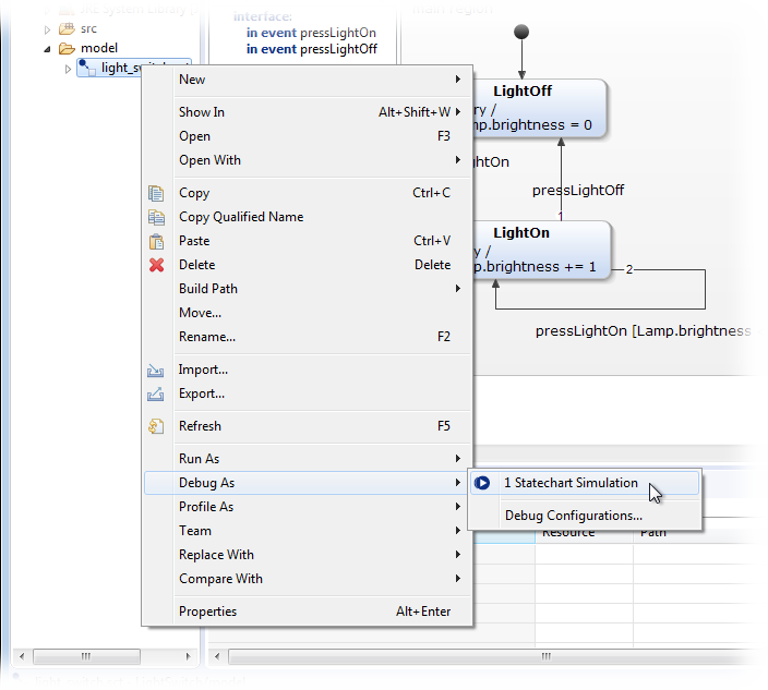
Starting a simulation in debug mode
Setting a breakpoint Copy link to clipboard
- Right-click on a state or transition. The context menu opens.
- Select Toggle breakpoint from the context menu, see Figure "Setting a breakpoint".
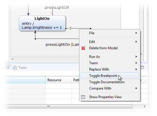
Setting a breakpoint
States and transitions with a breakpoint are labeled with a
 symbol.
Figure "Breakpoints on transition and state" shows an example.
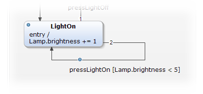
Breakpoints on transition and state
Hitting a breakpoint Copy link to clipboard
If the simulation runs into a state with a breakpoint, the state’s entry actions, if any, are executed. After that, execution of the state machine is suspended. The state is highlighted by a small green border.
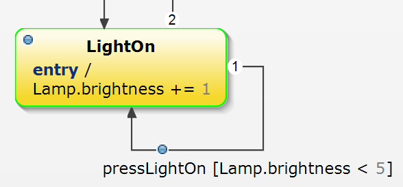
Highlighting a suspended state
If the simulation runs into a transition with a breakpoint, execution of the state machine is suspended. The transition is highlighted by drawing the transition arc in green. The transition’s actions, if any, are executed when the state machine is resumed.
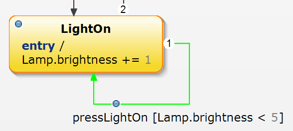
Highlighting a suspended transition
Continuing the simulation Copy link to clipboard
In order to continue from a breakpoint, you have two options:
- To continue execution, click on the resume button
 in the simulation view. The statechart simulation continues until the next breakpoint is hit or the simulation is terminated.
- To execute only the next run-cycle of the simulation and then suspend again, click on the step-over button
 in the simulation view.
Using the breakpoints view Copy link to clipboard
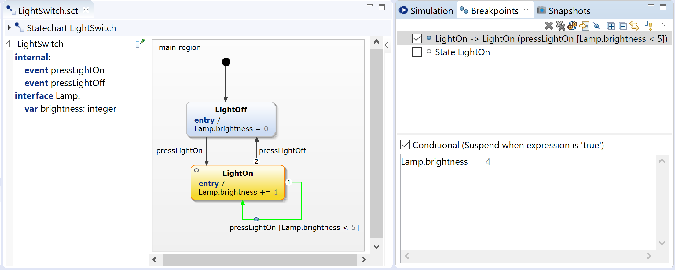
The breakpoints view shows a list of all breakpoints. The respective breakpoint name identifies the state or transition in question. See figure "Breakpoints view" for an example.
You can use the breakpoints view for disabling, enabling, and removing breakpoints as well as for defining conditional breakpoints.
The Breakpoints view
Enabling and disabling breakpoints Copy link to clipboard
A breakpoint is either enabled or disabled.
- An
enabled breakpoint causes the statechart simulation to suspend when reaching it. In the statechart and in the breakpoints view, an enabled breakpoint is visualized by a filled light blue circle with a grey border:
 .
.
- A
disabled breakpoint is ignored by the statechart simulation. In the statechart and in the breakpoints view, a disabled breakpoint is visualized by a hollow circle with a grey border:
 .
.
Figure "Breakpoints view" shows an enabled and a disabled breakpoint in the statechart editor and in the breakpoints view, respectively.
You can instruct the statechart simulation to
skip all breakpoints by clicking on the
![Button [disengaged]: Skip all breakpoints Button [disengaged]: Skip all breakpoints](https://www.itemis.com/hubfs/solutions/itemis-create/documentation/images/advsim_button_breakpoint_skip_disengaged.png) button in the breakpoints view. The button will appear “pressed”, and while it is, the “skip breakpoints” functionality is engaged. That means, the simulation will not suspend at any breakpoint.
button in the breakpoints view. The button will appear “pressed”, and while it is, the “skip breakpoints” functionality is engaged. That means, the simulation will not suspend at any breakpoint.
This is different from
disabling all breakpoints, in that each breakpoint keeps its state of being enabled or disabled. Once you disengage the skip breakpoints functionality by clicking on the
![Button [engaged]: Skip all breakpoints Button [engaged]: Skip all breakpoints](https://www.itemis.com/hubfs/solutions/itemis-create/documentation/images/advsim_button_breakpoint_skip_engaged.png) button again, the simulation will suspend again at enabled breakpoints and will not suspend at disabled breakpoints.
button again, the simulation will suspend again at enabled breakpoints and will not suspend at disabled breakpoints.
Removing breakpoints Copy link to clipboard
In order to remove
some breakpoints, select these breakpoints in the breakpoints view, then click on the
 button. The selected breakpoints will be removed.
To remove
all breakpoints, click on the
 button
Conditional breakpoints Copy link to clipboard
A conditional breakpoint has an associated condition and suspends the simulation only if
- that condition is fulfilled (true) and
- the breakpoint is enabled.
In order to attach a condition to a breakpoint, proceed as follows:
- In the breakpoints view, select the breakpoint in question.
- Check the Conditional checkbox, see figure "Breakpoints view" in the lower right area. The associated text field becomes writable.
- Enter the condition into the text field. Like in the statechart editor, a content assist is available when pressing
[Ctrl+Space]. The expression you entered into the text field is validated automatically. In the example shown in figure "Breakpoints view", the transition suspends the simulation only if the variable brightness has a value of 4.
Debugging a statechart Copy link to clipboard
Changing variable values Copy link to clipboard
In the suspended status of a statechart simulation, you can change variable values using the simulation view. When continuing execution – see section Continuing the simulation – you can observe how your state machine behaves with those modified values.
Raising multiple events simultaneously Copy link to clipboard
If you click on an event’s name in the simulation view to raise that event in normal simulation, i.e., while execution isn’t suspended, the state machine processes that event and takes the corresponding transition, if any.
However, while the simulation is suspended, you can raise multiple events, without instant execution. Once execution resumes, the state machine’s behavior depends on its execution scheme:
- In the cycle-based execution scheme, both events are handled at the same time, or, to be more exact, in the same run-to-completion step (RTC).
- In the event-driven execution scheme, each of the two events will trigger a run-to-completion step (RTC) of its own.
Let’s have a look at an example. Please note that this example uses the cycle-based execution scheme! This is important, because in the the event-driven case the state machine’s behavior would be different.
Let’s consider that you want to press the "light on" and "light off" buttons at the same time and want to observe what happens. Figure "Raising multiple events simultaneously" shows the scenario:
![Raising multiple events simultaneously [1] Raising multiple events simultaneously [1]](https://www.itemis.com/hubfs/solutions/itemis-create/documentation/images/advsim_040_multiple_events_010_events_not_raised.png)
Raising multiple events simultaneously [1]
- The simulation has encountered a breakpoint at the LightOn state and has been suspended there.
- The simulation view shows the
pressLightOn and the
pressLightOff events. Both events are labeled with a
![Symbol: Event [not raised] Symbol: Event [not raised]](https://www.itemis.com/hubfs/solutions/itemis-create/documentation/images/symbol_event.png) symbol, meaning the respective event is not raised.
symbol, meaning the respective event is not raised.
![Raising multiple events simultaneously [2] Raising multiple events simultaneously [2]](https://www.itemis.com/hubfs/solutions/itemis-create/documentation/images/advsim_040_multiple_events_020_events_raised.png)
Raising multiple events simultaneously [2]
- Clicking on an event raises it and adds a blue triangle to the event symbol:
![Symbol: Event [raised] Symbol: Event [raised]](https://www.itemis.com/hubfs/solutions/itemis-create/documentation/images/symbol_event_raised.png) . Since the simulation remains suspended, the user can raise multiple events.
. Since the simulation remains suspended, the user can raise multiple events.
Both events are raised and will be handled by the state machine during the next run-to-completion step. The latter will be performed as soon as the user clicks on the step-over button
 or the resume button
 .
.
Please note: Under the even-driven execution scheme, multiple events are never processed at the same time. Each event triggers a separate RTC.
Please note: While the execution is still suspended, you can “unraise” an already raised event by clicking on the event symbol
a second time. The blue triangle will disappear, and upon continuation of the simulation the event will not be handled.
Transition priorities Copy link to clipboard
It is important to understand that in the event-driven execution scheme there is a queue of events, while in the cycle-based scheme there isn’t. If in the latter case multiple events occur simultaneously, they are all present at the same time, and the state machine has to figure out which event should trigger which transition. For example, what should the light switch state machine do, if it is in the LightOn state and both events, pressLightOn and pressLightOff, have been raised simultaneously?
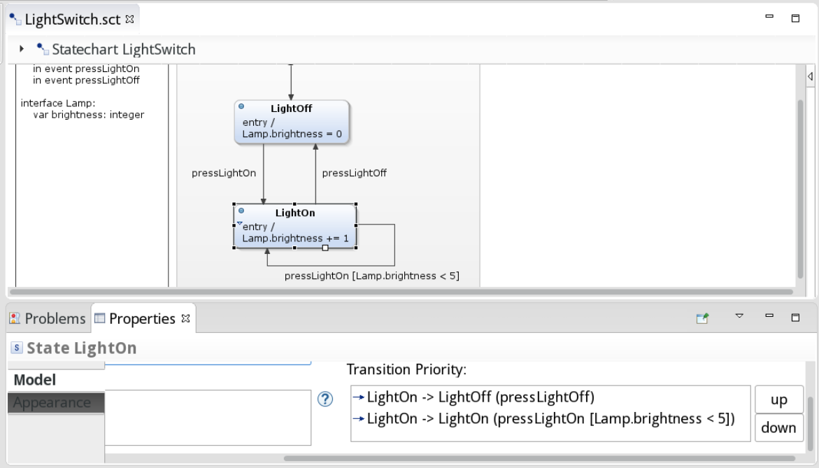
The answer is transition priorities. The state machine always consults the active state’s transitions in a well-defined order, it fires the first matching transition it encounters, and it forgets about the rest. Transition priorities are specified in the corresponding property of the respective state, see figure "Transition priorities". You can change these priorities, and thus the order the transitions are being checked, by selecting a transition and moving it up or down by clicking on the respective button.
The first transition whose condition is fulfilled will be executed. Under the cycle-based execution scheme, all remaining events are quashed. In the light switch example as shown in figure "Transition priorities", the pressLightOff event would “win” and trigger a transition from the LightOn to the LightOff state, while the pressLightOff event would be discarded.
Transition priorities
p.